Orbiting Carbon Observatory-2OCO-2
Calibration is a critical step for all remote-sensed data. For OCO-2, the calibration steps ensure that the data received from the space borne instrument are converted into meaningful and accurate radiance in physical units for science and application purposes.
To accurately retrieve the O2 and CO2 concentrations, it is necessary to know:
Continuing calibration exercises during space operations ensure OCO-2 obtains bias-free radiance measurements. Accurate radiance measurements are crucial to retrieve XCO2, or the amount of CO2 in the measured space, with the accuracy and precision (<0.25% or 1 ppm) needed to determine where CO2 is absorbed or released on the ground. This aspect of the OCO-2 mission is vital as these CO2 sources and sinks are inferred from small variations in XCO2.
The OCO-2 instrument focal planes record the “brightness” of the incident spectral radiances as raw data numbers (dN), ranging from 0 to 65535 (note they have no units). These data numbers are converted into physical units of photons per square meter per steradian per second per micron through radiometric calibration.
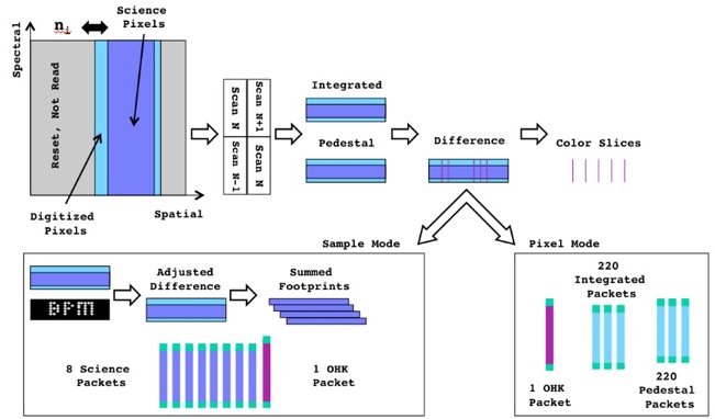
OCO-2 Data Conversion Diagram
The conversion of instrument output into physical measures generated by the calibration process are the central data reported in the OCO-2 Level 1B Product.
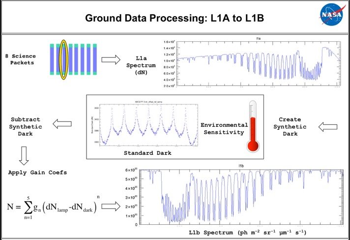
Data Processing flow chart from Level 1A to L1B
Detailed laboratory tests that were performed pre-launch include:
The characterization of the instrument on the ground before launch yielded the initial set of parameters required to convert instrument data numbers into incident radiances. Once the instrument was in flight, data was routinely collected to track changes with time, including:
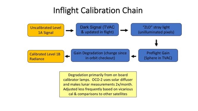
Inflight Calibration Chain
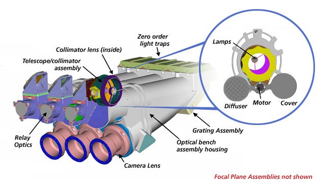
The area highlighted in the blue circle provides a physical overview of the On Board Calibrator that overlays the instrument telescope/collimator assembly.
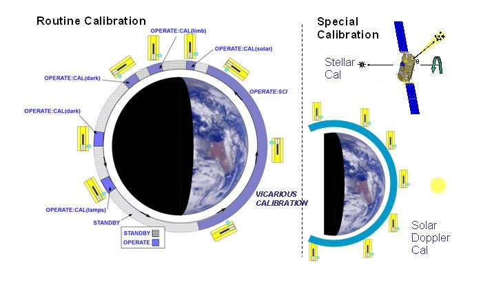
On orbit data collections in support of calibration
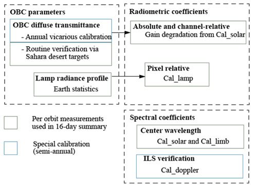
Calibration parameter summary